PIC Basic Compiler Examples
This page contains several complete examples where PIC Simulator IDE integrated PIC Basic compiler is used to get the HEX file
ready to be programmed into a real PIC chip.
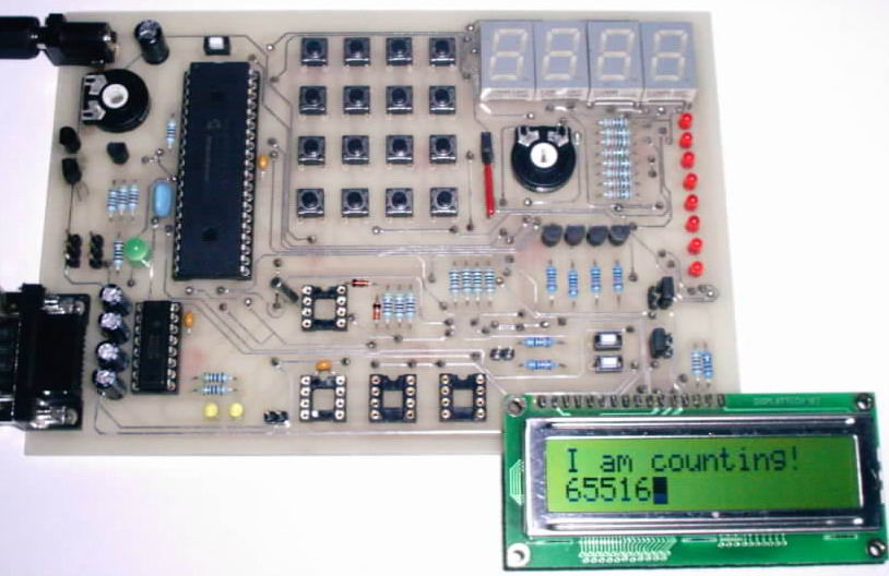
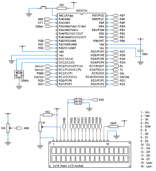
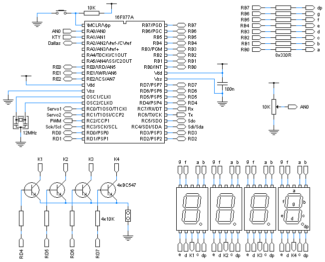
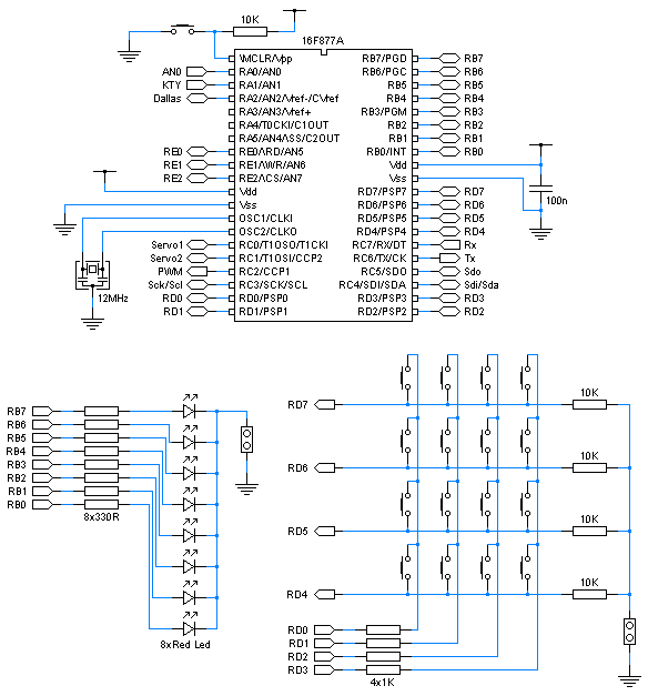
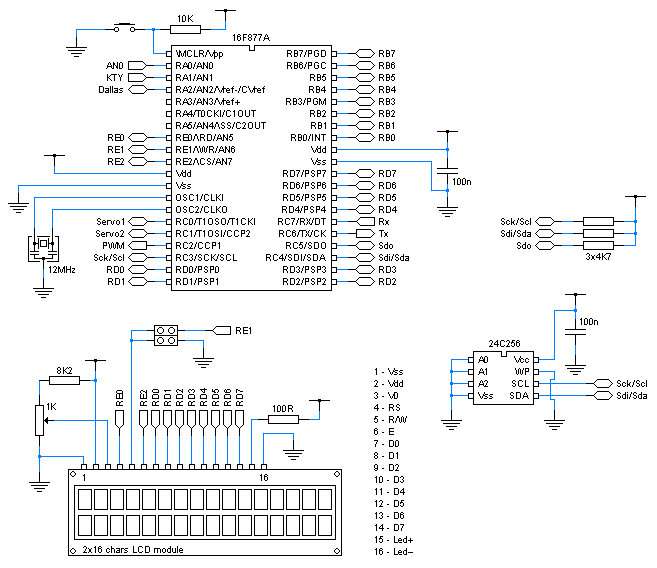
All examples presented on this page were tested on the development board for PIC16F877A microcontroller that is documented
on the Hardware Projects page. All schematics are subsections of the schematics of the whole development board.
Example 1: Basic LCD test Example 2: Reading analog input Example 3: Playing with LEDs Example 4: 7-segment displays Example 5: 4x4 matrix keypad Example 6: PWM regulation of LED light intensity Example 7: RS-232 communication with PC Example 8: I2C communication with 24C256 eeprom Example 9: I2C communication with PCF8583 real time clock Example 10: Measuring temperature with DS18S20
Example 1: Basic LCD test
Schematics:
view
The photo of the program execution:
view
Go to examples menu
Example 2: Reading analog input
Schematics:
view
The photo of the program execution:
view
Basic source program: Copy code
#define CONF_WORD = 0x3f72
#define CLOCK_FREQUENCY = 12
All_Digital
ADCON1 = 0x0e
#define LCD_BITS = 8
#define LCD_DREG = PORTD
#define LCD_DBIT = 0
#define LCD_RSREG = PORTE
#define LCD_RSBIT = 0
#define LCD_RWREG = PORTE
#define LCD_RWBIT = 1
#define LCD_EREG = PORTE
#define LCD_EBIT = 2
#define LCD_READ_BUSY_FLAG = 1
Lcdinit
Dim an0 As Word
loop:
ADC_Read 0, an0
Lcdcmdout LcdClear
Lcdout "Analog input AN0"
Lcdcmdout LcdLine2Home
Lcdout "Value: ", #an0
WaitMs 250
Goto loop
Go to examples menu
Example 3: Playing with LEDs
Schematics:
view
The photo of the program execution:
view
Basic source program: Copy code
#define CONF_WORD = 0x3f72
#define CLOCK_FREQUENCY = 12
All_Digital
Dim i As Byte
TRISB = 0
loop:
For i = 0 To 255
PORTB = i
WaitMs 100
Next i
Goto loop
Go to examples menu
Example 4: 7-segment displays
Schematics:
view
The photo of the program execution:
view
Basic source program: Copy code
#define CONF_WORD = 0x3f72
#define CLOCK_FREQUENCY = 12
All_Digital
ADCON1 = 0x0e
Dim digit As Byte 'input variable for GETMASK subroutine
Dim digit1 As Byte 'current digit1
Dim digit2 As Byte 'current digit2
Dim digit3 As Byte 'current digit3
Dim digit4 As Byte 'current digit4
Dim mask As Byte 'output variable from GETMASK subroutine
Dim mask1 As Byte 'current digit1 mask
Dim mask2 As Byte 'current digit2 mask
Dim mask3 As Byte 'current digit3 mask
Dim mask4 As Byte 'current digit4 mask
Dim phase As Byte
Dim an0 As Word
Dim i As Byte
Symbol d1enable = PORTD.4 'enable line for display1
Symbol d2enable = PORTD.5 'enable line for display2
Symbol d3enable = PORTD.6 'enable line for display3
Symbol d4enable = PORTD.7 'enable line for display4
TRISB = %00000000 'set PORTB pins as outputs
TRISD.4 = 0 'set RD4 pin as output
TRISD.5 = 0 'set RD5 pin as output
TRISD.6 = 0 'set RD6 pin as output
TRISD.7 = 0 'set RD7 pin as output
d1enable = False
d2enable = False
d3enable = False
d4enable = False
mask1 = 0
mask2 = 0
mask3 = 0
mask4 = 0
phase = 1
INTCON.T0IE = 1 'enable Timer0 interrupts
INTCON.GIE = 1 'enable all un-masked interrupts
OPTION_REG.T0CS = 0 'set Timer0 clock source to internal instruction cycle clock
loop:
ADC_Read 0, an0 'AN0 - value to be displayed
digit1 = an0 / 1000 'get current digit1
an0 = an0 Mod 1000
digit2 = an0 / 100 'get current digit2
an0 = an0 Mod 100
digit3 = an0 / 10 'get current digit3
an0 = an0 Mod 10
digit4 = an0 'get current digit4
TMR0 = 0 'reset Timer0 to prevent its interrupt before both masks are determined
digit = digit1
Gosub getmask 'get mask for digit1
mask1 = mask
digit = digit2
Gosub getmask 'get mask for digit2
mask2 = mask
digit = digit3
Gosub getmask 'get mask for digit3
mask3 = mask
digit = digit4
Gosub getmask 'get mask for digit4
mask4 = mask
Gosub show1 'display new mask
Gosub show2 'display new mask
Gosub show3 'display new mask
Gosub show4 'display new mask
WaitMs 500
Goto loop
End
On Interrupt 'Timer0 interrupt routine
If phase = 1 Then Gosub show1
If phase = 2 Then Gosub show2
If phase = 3 Then Gosub show3
If phase = 4 Then Gosub show4
phase = phase + 1
If phase = 5 Then phase = 1
INTCON.T0IF = 0 'enable new TMR0 interrupts
Resume
getmask: 'get appropriate 7-segment mask for input digit
mask = LookUp(0x3f, 0x06, 0x5b, 0x4f, 0x66, 0x6d, 0x7d, 0x07, 0x7f, 0x6f), digit
Return
show1: 'show digit1 on its display
d1enable = False
d2enable = False
d3enable = False
d4enable = False
PORTB = mask1
d1enable = True
Return
show2: 'show digit2 on its display
d1enable = False
d2enable = False
d3enable = False
d4enable = False
PORTB = mask2
d2enable = True
Return
show3: 'show digit3 on its display
d1enable = False
d2enable = False
d3enable = False
d4enable = False
PORTB = mask3
d3enable = True
Return
show4: 'show digit4 on its display
d1enable = False
d2enable = False
d3enable = False
d4enable = False
PORTB = mask4
d4enable = True
Return
Go to examples menu
Example 5: 4x4 matrix keypad
Schematics:
view
Basic source program: Copy code
#define CONF_WORD = 0x3f72
#define CLOCK_FREQUENCY = 12
All_Digital
Symbol raw1 = RD7
Symbol raw2 = RD6
Symbol raw3 = RD5
Symbol raw4 = RD4
Symbol col1 = RD0
Symbol col2 = RD1
Symbol col3 = RD2
Symbol col4 = RD3
TRISD = 0xf0
TRISB = 0
Dim button As Byte
loop:
Gosub get_button
PORTB = button
Goto loop
End
get_button:
button = 0
col1 = 1
If raw1 = 1 Then button = 1
If raw2 = 1 Then button = 5
If raw3 = 1 Then button = 9
If raw4 = 1 Then button = 13
col1 = 0
col2 = 1
If raw1 = 1 Then button = 2
If raw2 = 1 Then button = 6
If raw3 = 1 Then button = 10
If raw4 = 1 Then button = 14
col2 = 0
col3 = 1
If raw1 = 1 Then button = 3
If raw2 = 1 Then button = 7
If raw3 = 1 Then button = 11
If raw4 = 1 Then button = 15
col3 = 0
col4 = 1
If raw1 = 1 Then button = 4
If raw2 = 1 Then button = 8
If raw3 = 1 Then button = 12
If raw4 = 1 Then button = 16
col4 = 0
Return
Go to examples menu
Example 6: PWM regulation of LED light intensity
Schematics:
view
Basic source program: Copy code
#define CONF_WORD = 0x3f72
#define CLOCK_FREQUENCY = 12
All_Digital
ADCON1 = 0x0e
Dim duty As Byte
PWMon 1, 9
loop:
ADC_Read 0, duty
WaitMs 50
PWMduty 1, duty
Goto loop
Go to examples menu
Example 7: RS-232 communication with PC
Schematics:
view
The photo of the program execution:
view
The screenshot of the PIC Simulator IDE serial port terminal:
view
Basic source program: Copy code
#define CONF_WORD = 0x3f72
#define CLOCK_FREQUENCY = 12
All_Digital
#define LCD_BITS = 8
#define LCD_DREG = PORTD
#define LCD_DBIT = 0
#define LCD_RSREG = PORTE
#define LCD_RSBIT = 0
#define LCD_RWREG = PORTE
#define LCD_RWBIT = 1
#define LCD_EREG = PORTE
#define LCD_EBIT = 2
#define LCD_READ_BUSY_FLAG = 1
Lcdinit
Dim i As Byte
UART_Init 19200
WaitMs 1000
For i = 20 To 0 Step -1
UART_Write "Number: ", #i, CrLf
Lcdcmdout LcdClear
Lcdout "Number: ", #i
WaitMs 1000
Next i
loop:
UART_Read i
UART_Write "Number: ", #i, CrLf
Lcdcmdout LcdClear
Lcdout "Number: ", #i
Goto loop
Go to examples menu
Example 8: I2C communication with 24C256 eeprom
Schematics:
view
The photo of the program execution:
view
Basic source program: Copy code
#define CONF_WORD = 0x3f72
#define CLOCK_FREQUENCY = 12
All_Digital
#define LCD_BITS = 8
#define LCD_DREG = PORTD
#define LCD_DBIT = 0
#define LCD_RSREG = PORTE
#define LCD_RSBIT = 0
#define LCD_RWREG = PORTE
#define LCD_RWBIT = 1
#define LCD_EREG = PORTE
#define LCD_EBIT = 2
#define LCD_READ_BUSY_FLAG = 1
Lcdinit
Symbol scl = PORTC.3
Symbol sda = PORTC.4
Dim addr As Word
Dim data As Byte
For addr = 0 To 31
Lcdcmdout LcdClear
data = 255 - addr
I2CWrite sda, scl, 0xa0, addr, data
Lcdout "Write To EEPROM"
Lcdcmdout LcdLine2Home
Lcdout "(", #addr, ") = ", #data
WaitMs 500
Next addr
For addr = 0 To 31
Lcdcmdout LcdClear
I2CRead sda, scl, 0xa0, addr, data
Lcdout "Read From EEPROM"
Lcdcmdout LcdLine2Home
Lcdout "(", #addr, ") = ", #data
WaitMs 500
Next addr
Go to examples menu
Example 9: I2C communication with PCF8583 real time clock
Schematics:
view
The photo of the program execution:
view
Basic source program: Copy code
#define CONF_WORD = 0x3f72
#define CLOCK_FREQUENCY = 12
All_Digital
#define LCD_BITS = 8
#define LCD_DREG = PORTD
#define LCD_DBIT = 0
#define LCD_RSREG = PORTE
#define LCD_RSBIT = 0
#define LCD_RWREG = PORTE
#define LCD_RWBIT = 1
#define LCD_EREG = PORTE
#define LCD_EBIT = 2
#define LCD_READ_BUSY_FLAG = 1
Lcdinit
Symbol scl = PORTC.3
Symbol sda = PORTC.4
Dim addr As Byte
Dim data As Byte
Dim sec As Byte
Dim min As Byte
Dim hour As Byte
Dim day As Byte
Dim month As Byte
Dim year As Byte
Dim d_hi As Byte
Dim d_lo As Byte
WaitMs 1000
addr = 2
I2CWrite sda, scl, 0xa2, addr, 0
addr = 3
I2CWrite sda, scl, 0xa2, addr, 0x55
addr = 4
I2CWrite sda, scl, 0xa2, addr, 0x23
addr = 5
I2CWrite sda, scl, 0xa2, addr, 0xb1
addr = 6
I2CWrite sda, scl, 0xa2, addr, 0x12
loop:
addr = 2
I2CRead sda, scl, 0xa2, addr, sec
addr = 3
I2CRead sda, scl, 0xa2, addr, min
addr = 4
I2CRead sda, scl, 0xa2, addr, hour
addr = 5
I2CRead sda, scl, 0xa2, addr, day
year = 0
year.0 = day.6
year.1 = day.7
day.6 = 0
day.7 = 0
addr = 6
I2CRead sda, scl, 0xa2, addr, month
month.5 = 0
month.6 = 0
month.7 = 0
Lcdcmdout LcdClear
Lcdout "Time: "
data = hour
Gosub print
Lcdout ":"
data = min
Gosub print
Lcdout ":"
data = sec
Gosub print
Lcdcmdout LcdLine2Home
Lcdout "Date: "
data = day
Gosub print
Lcdout "/"
data = month
Gosub print
Lcdout "/200", #year
WaitMs 200
Goto loop
End
print:
d_hi = data / 16
d_lo = data Mod 16
If d_hi < 10 Then
Lcdout #d_hi
Else
Lcdout "X"
Endif
If d_lo < 10 Then
Lcdout #d_lo
Else
Lcdout "X"
Endif
Return
Go to examples menu
Example 10: Measuring temperature with DS18S20
Schematics:
view
The photo of the program execution:
view
Basic source program: Copy code
#define CONF_WORD = 0x3f72
#define CLOCK_FREQUENCY = 12
All_Digital
#define LCD_BITS = 8
#define LCD_DREG = PORTD
#define LCD_DBIT = 0
#define LCD_RSREG = PORTE
#define LCD_RSBIT = 0
#define LCD_RWREG = PORTE
#define LCD_RWBIT = 1
#define LCD_EREG = PORTE
#define LCD_EBIT = 2
#define LCD_READ_BUSY_FLAG = 1
Lcdinit
#define 1WIRE_REG = PORTA
#define 1WIRE_BIT = 2
Dim temp As Byte
Dim sign As Byte
Dim temp2 As Bit
loop:
DS18S20Start
WaitMs 1000
DS18S20ReadT temp, sign
Lcdcmdout LcdClear
If sign > 0 Then
Lcdout "-"
temp = 255 - temp
temp = temp + 1
Endif
temp2 = temp.0
temp = temp / 2
Lcdout #temp
If temp2 = 1 Then
Lcdout ".5"
Else
Lcdout ".0"
Endif
WaitMs 500
Goto loop
Basic source program (low level 1-wire): Copy code
#define CONF_WORD = 0x3f72
#define CLOCK_FREQUENCY = 12
All_Digital
#define LCD_BITS = 8
#define LCD_DREG = PORTD
#define LCD_DBIT = 0
#define LCD_RSREG = PORTE
#define LCD_RSBIT = 0
#define LCD_RWREG = PORTE
#define LCD_RWBIT = 1
#define LCD_EREG = PORTE
#define LCD_EBIT = 2
#define LCD_READ_BUSY_FLAG = 1
Lcdinit
#define 1WIRE_REG = PORTA
#define 1WIRE_BIT = 2
Dim finish As Bit
Dim temp As Byte
Dim sign As Byte
Dim temp2 As Bit
loop:
1wireInit
1wireSendByte 0xcc, 0x44
WaitMs 1
loop2:
1wireGetBit finish
If finish = 0 Then Goto loop2
1wireInit
1wireSendByte 0xcc, 0xbe
1wireGetByte temp, sign
Lcdcmdout LcdClear
If sign > 0 Then
Lcdout "-"
temp = 255 - temp
temp = temp + 1
Endif
temp2 = temp.0
temp = temp / 2
Lcdout #temp
If temp2 = 1 Then
Lcdout ".5"
Else
Lcdout ".0"
Endif
WaitMs 500
Goto loop
Go to examples menu

